
The CAN Bus Protocol Tutorial gives an overview of the ISO 11898-1 and ISO 11898-2 controller area network standards. This tutorial provides a great introduction to the fundamentals of CAN (controller area network) as it is used in automotive design, industrial automation controls, and many more applications.
Our updated 8-part video course sets a new standard in CAN training.
CAN is short for ‘controller area network’. Controller area network is an electronic communication bus defined by the ISO 11898 standards. Those standards define how communication happens, how wiring is configured and how messages are constructed, among other things. Collectively, this system is referred to as a CAN bus.
To get deeper into the details of CAN, the CAN bus is a broadcast type of bus. This means that all nodes can “hear” all transmissions. There is no way to send a message to just a specific node; all nodes will invariably pick up all traffic. The CAN hardware, however, provides local filtering so that each node may react only on the interesting messages. We’ll discuss this more in Section 2, “CAN Messages”.
We’ll also discuss how the bus uses Non-Return To Zero (NRZ) with bit-stuffing. In this system, the modules are connected to the bus in a wired-and fashion: if just one node is driving the bus to a logical 0, then the whole bus is in that state regardless of the number of nodes transmitting a logical 1.
The CAN standard defines four different message types. The messages uses a clever scheme of bit-wise arbitration to control access to the bus, and each message is tagged with a priority.
The CAN standard also defines an elaborate scheme for error handling and confinement which is described in more detail in Section 7, “CAN Error Handling”.
Bit timing and clock synchronization is discussed in Section 6 of this tutorial. Here’s a bit timing calculator you can use to calculate the CAN bus parameters and register settings.
CAN bus wiring may be implemented using different physical layers (Section 3), some of which are described here, and there are also a fair number of CAN bus connector types (Section 5) in use. We also provide a number of oscilloscope pictures (Section 4) for those interested in the details of a message.
The CAN bus is a broadcast type of bus. This means that all nodes can ‘hear’ all transmissions. There is no way to send a message to just a specific node; all nodes will invariably pick up all traffic. The CAN hardware, however, provides local filtering so that each node may react only on the interesting messages.
The CAN messages
CAN uses short messages – the maximum utility load is 94 bits. There is no explicit address in the messages; instead, the messages can be said to be contents-addressed, that is, their contents implicitly determines their address.
Message Types
There are four different message types (or ‘frames’) on a CAN bus:
Summary: “Hello everyone, here’s some data labeled X, hope you like it!”
The Data Frame is the most common message type. It comprises the following major parts (a few details are omitted for the sake of brevity):
Note 1: It is worth noting that the presence of an Acknowledgement Bit on the bus does not mean that any of the intended addressees has received the message. The only thing we know is that one or more nodes on the bus has received it correctly.
Note 2: The Identifier in the Arbitration Field is not, despite of its name, necessarily identifying the contents of the message.

A CAN 2.0A (“standard CAN”) Data Frame.

A CAN 2.0B (“extended CAN”) Data Frame.
The Remote Frame is just like the Data Frame, with two important differences:
The intended purpose of the Remote Frame is to solicit the transmission of the corresponding Data Frame. If, say, node A transmits a Remote Frame with the Arbitration Field set to 234, then node B, if properly initialized, might respond with a Data Frame with the Arbitration Field also set to 234.
Remote Frames can be used to implement a request-response type of bus traffic management. In practice, however, the Remote Frame is little used. It is also worth noting that the CAN standard does not prescribe the behaviour outlined here. Most CAN controllers can be programmed either to automatically respond to a Remote Frame, or to notify the local CPU instead.
There’s one catch with the Remote Frame: the Data Length Code must be set to the length of the expected response message. Otherwise the arbitration will not work.

A Remote Frame (2.0A type)
Sometimes it is claimed that the node responding to the Remote Frame is starting its transmission as soon as the identifier is recognized, thereby “filling up” the empty Remote Frame. This is not the case.
Summary: (everyone, aloud) “OH DEAR, LET’S TRY AGAIN”
Simply put, the Error Frame is a special message that violates the framing rules of a CAN message. It is transmitted when a node detects a fault and will cause all other nodes to detect a fault – so they will send Error Frames, too. The transmitter will then automatically try to retransmit the message. There is an elaborate scheme of error counters that ensures that a node can’t destroy the bus traffic by repeatedly transmitting Error Frames.
The Error Frame consists of an Error Flag, which is 6 bits of the same value (thus violating the bit-stuffing rule) and an Error Delimiter, which is 8 recessive bits. The Error Delimiter provides some space in which the other nodes on the bus can send their Error Flags when they detect the first Error Flag.

Summary: “I’m a very busy little 82526, could you please wait for a moment?”
The Overload Frame is mentioned here just for completeness. It is very similar to the Error Frame with regard to the format and it is transmitted by a node that becomes too busy. The Overload Frame is not used very often, as today’s CAN controllers are clever enough not to use it. In fact, the only controller that will generate Overload Frames is the now obsolete 82526.
Originally, the CAN standard defined the length of the Identifier in the Arbitration Field to eleven (11) bits. Later on, customer demand forced an extension of the standard. The new format is often called Extended CAN and allows no less than twenty-nine (29) bits in the Identifier. To differentiate between the two frame types, a reserved bit in the Control Field was used.
The standards are formally called
New CAN controllers today are usually of the 2.0B type. A 1.x or 2.0A type controller will get very upset if it receives messages with 29 arbitration bits. A 2.0B passive type controller will tolerate them, acknowledge them if they are correct and then – discard them; a 2.0B active type controller can both transmit and receive them.
Controllers implementing 2.0B and 2.0A (and 1.x) are compatible – and may be used on the same bus – as long as the controllers implementing 2.0B refrain from sending extended frames!
Sometimes people advocate that standard CAN is “better” than Extended CAN because there is more overhead in the Extended CAN messages. This is not necessarily true. If you use the Arbitration Field for transmitting data, then Extended CAN may actually have a lower overhead than Standard CAN has.
The terms “Basic CAN” and “Full CAN” originate from the childhood of CAN. Once upon a time there was the Intel 82526 CAN controller which provided a DPRAM-style interface to the programmer. Then came along Philips with the 82C200 which used a FIFO- (queue-) oriented programming model and limited filtering abilities. To distinguish between the two programming models, people for some reason termed the Intel way as “Full CAN” and the Philips way as “Basic CAN”. Today, most CAN controllers allow for both programming models, so there is no reason to use the terms “Full CAN” and “Basic CAN” – in fact, these terms can cause confusion and should be avoided.
Of course, a “Full CAN” controller can communicate with a “Basic CAN” controller and vice versa. There are no compatibility problems.
The message arbitration (the process in which two or more CAN controllers agree on who is to use the bus) is of great importance for the actually available bandwidth for data transmission.
Any CAN controller may start a transmission when it has detected an idle bus. This may result in two or more controllers starting a message (almost) at the same time. The conflict is resolved in the following way. The transmitting nodes monitor the bus while they are sending. If a node detects a dominant level when it is sending a recessive level itself, it will immediately quit the arbitration process and become a receiver instead. The arbitration is performed over the whole Arbitration Field and when that field has been sent, exactly one transmitter is left on the bus. This node continues the transmission as if nothing had happened. The other potential transmitters will try to retransmit their messages when the bus becomes available next time. No time is lost in the arbitration process.
An important condition for this bit-wise arbitration to succeed is that no two nodes may transmit the same Arbitration Field. There is one exception to this rule: if the message contains no data, then any node may transmit that message.
Since the bus is wired-and and a Dominant bit is logically 0, it follows that the message with the numerically lowest Arbitration Field will win the arbitration.
Q: What happens if a node is alone on the bus and tries to transmit?
A: The node will, of course, win the arbitration and happily proceeds with the message transmission. But when the time comes for acknowledging… no node will send a dominant bit during the ACK slot, so the transmitter will sense an ACK error, send an error flag, increase its transmit error counter by 8 and start a retransmission. This will happen 16 times; then the transmitter will go error passive. By a special rule in the error confinement algorithm, the transmit error counter is not further increased if the node is error passive and the error is an ACK error. So the node will continue to transmit forever, at least until someone acknowledges the message.
It is worth noting once again that there is no explicit address in the CAN messages. Each CAN controller will pick up all traffic on the bus, and using a combination of hardware filters and software, determine if the message is “interesting” or not.
In fact, there is no notion of message addresses in CAN. Instead, the contents of the messages is identified by an identifier which is present somewhere in the message. CAN messages are said to be “contents-addressed”.
A conventional message address would be used like “Here’s a message for node X”. A contents-addressed message is like “Here’s a message containing data labeled X”. The difference between these two concepts is small but significant.
The contents of the Arbitration Field is, per the Standard, used to determine the message’s priority on the bus. All CAN controllers will also use the whole (some will use just a part) of the Arbitration Field as a key in the hardware filtration process.
The Standard does not say that the Arbitration Field must be used as a message identifier. It’s nevertheless a very common usage.
We said that 11 (CAN 2.0A) or 29 (CAN 2.0B) bits is available in the Identifier. This is not entirely correct. Due to compability with a certain old CAN controller (guess which?), identifiers must not have the 7 most significant bits set to all ones, so only the identifiers 0..2031 are left for the 11-bit identifiers, and the user of 29-bit identifiers can use 532676608 different values.
Note that all other CAN controllers accept the “illegal” identifiers, so in a modern CAN system identifiers 2032..2047 can be used without restrictions.
The CAN bus uses Non-Return To Zero (NRZ) with bit-stuffing. There are two different signaling states: dominant (logically 0) and recessive (logically 1). These correspond to certain electrical levels which depend on the physical layer used (there are several.) The modules are connected to the bus in a wired-and fashion: if just one node is driving the bus to the dominant state, then the whole bus is in that state regardless of the number of nodes transmitting a recessive state.
A physical layer defines the electrical levels and signaling scheme on the bus, the cable impedance and similar things.
There are several different physical layers:
Different physical layers can not, as a rule, interoperate. Some combinations may work, or seem to work, under good conditions. For example, using both “high-speed” and “low-speed” transceivers on the same bus can work … sometimes.
A great many CAN transceiver chips are manufactured by NXP; alternative vendors include Bosch, Infineon, Texas Instruments and Vishay Siliconix.
A very common type is the 82C250 transceiver which implements the physical layer defined by ISO 11898. The 82C251 is an improved version.
A common transceiver for “low-speed CAN” is TJA1054 from NXP.
The maximum speed of a CAN bus, according to the standard, is 1 Mbit/second. Some CAN controllers will nevertheless handle higher speeds than 1Mbit/s and may be considered for special applications.
Low-speed CAN (ISO 11898-3, see above) can go up to 125 kbit/s.
Single-wire CAN can go up to around 50 kbit/s in its standard mode and, using a special high-speed mode used e.g. for ECU programming, up to around 100 kbit/s.
Be aware that some bus transceivers will not allow you to go below a certain bit rate. For example, using 82C250 or 82C251 you can go down to 10 kbit/s without problems, but if you use the TJA1050 instead you can’t go below around 50 kbit/s. Check the data sheet.
At a speed of 1 Mbit/s, a maximum cable length of about 40 meters (130 ft.) can be used. This is because the arbitration scheme requires that the wave front of the signal be able to propagate to the most remote node and back again before the bit is sampled. In other words, the cable length is restricted by the speed of light. A proposal to increase the speed of light has been considered but was turned down because of its inter-galactic consequences.
Other maximum cable lengths are (these values are approximate):
If optocouplers are used to provide galvanic isolation, the maximum bus length is decreased accordingly. Hint: use fast optocouplers, and look at the delay through the device, not at the specified maximum bit rate.
An ISO 11898 CAN bus must be terminated. This is done using a resistor of 120 Ohms in each end of the bus. The termination serves two purposes:
An ISO 11898 CAN bus must always be terminated regardless of its speed. I’ll repeat this: an ISO 11898 CAN bus must always be terminated regardless of its speed. For laboratory work just one terminator might be enough. If your CAN bus works even though you haven’t put any terminators on it, you are just lucky.
Note that other physical layers, such as “low-speed CAN”, single-wire CAN, and others, may or may not require termination. But your vanilla high-speed ISO 11898 CAN bus will always require at least one terminator.
The ISO 11898 prescribes that the cable impedance be nominally 120 Ohms, but an impedance in the interval of [108..132] Ohms is permitted.
There are not many cables in the market today that fulfill this requirement. There is a good chance that the allowed impedance interval will be broadened in the future.
ISO 11898 is defined for a twisted pair cable, shielded or unshielded. Work is in progress on the single-wire standard SAE J2411.
There is no standard at all for CAN bus connectors! Usually, each Higher Layer Protocol(!) defines one or a few preferred CAN bus connector types. Common types include
Here’s a picture from a perfectly normal ISO 11898 CAN bus, running at 1 Mbit/s. The transceiver is a 82C251; in other words, the physical layer is the one specified by ISO 11898.

The measurement was done between CAN_H and GND. Note that the quiescent and recessive bus voltages lie around 2.5 V. When a dominant bit is transmitted the voltage rises to around 3.5V.
Now here’s the same bus, but measurement is done between CAN_L and GND instead.

Here’s another message, sent at 125 kbit/s. The message’s (11-bit) identifier is 300, or 12c in hexadecimal. Look closely and you should be able to identify the first bits in the message.

Here’s a trickier picture. It shows the same message as above, still (11-bit) identifier 300 and still 125 kbit/s, but without termination on the CAN bus. The CAN cable was a short run of flat ribbon cable.
So, what’s happening? This is 125 kbit/s, so one bit is 8 microseconds.
Moral: Always terminate the CAN bus! The reflections will not necessarily hurt, but the bad shape of the edges will kill the communication.

Here’s the same CAN bus in another time scale. The CAN bus was around 2 decimeters (8 in.) long. The undershoot and ringing is visible but in this case clearly not important. This time the slow rising edge is the culprit.

Here’s the same setup, but this time both the transmitter and the receiver are error active.
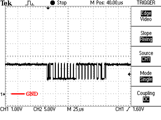
Here is yet another picture. In this setup there is only a single node on the (properly terminated) CAN bus. It’s trying to transmit a message, but no one is listening.
So what’s happening?

So what you see in the picture above is a message being transmitted, followed by a small pause which is the sum of the error flag, the error delimiter, the intermission and the suspend transmission. The message is then retransmitted and retransmitted and …
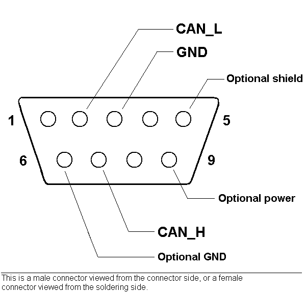
This connector layout is recommended by CiA and is pretty much the industrial standard.
If power is supplied, it shall be in the range +7..+13 V, 100 mA. Modules provide a male connector and have to connect pin 3 and 6 internally.
The pin numbering is valid for a male connector, viewed from the connector side, or for a female connector viewed from the soldering side. – To memorize the pinning, note that CAN_LOW has a LOW pin number and CAN_HIGH has a HIGH pin number.


Used by both DeviceNet and SDS and happens to be compatible between these two protocols.
The modules have male connectors. The supplied power is 24V +- 1%.
Note: in the DeviceNet specification version 1.x, the female connector in figure 9.13 has the numbers in wrong order. Specification 2.0 and later versions has got it right.
Recommended by CANHUG for use in mobile hydraulics applications.
Module side male, bus side female. There is currently no recommendation as to the supplied power.
Each bit on the CAN bus is, for timing purposes, divided into at least 4 quanta. The quanta are logically divided into four groups or segments:

Here is a picture of a CAN data bit.
The Synchronization Segment, which always is one quantum long, is used for synchronization of the clocks. A bit edge is expected to take place here when the data changes on the bus.
The Propagation Segment is needed to compensate for the delay in the bus lines.
Calculate all possible sets of CAN bus parameters for a given input frequency and a given bus speed.
The Phase Segments may be shortened (Phase Segment 1) or lengthened (Phase Segment 2) if necessary to keep the clocks in sync. The bus levels are sampled at the border between Phase Segment 1 and Phase Segment 2.
Most CAN controllers also provide an option to sample three times during a bit. In this case, the sampling occurs on the borders of the two quanta that precedes the sampling point, and the result is subject to majority decoding (at least this is the case for the 82527).
In order to adjust the on-chip bus clock, the CAN controller may shorten or prolong the length of a bit by an integral number of quanta. The maximum value of these bit time adjustments are termed the Synchronization Jump Width, SJW.
Hard synchronization occurs on the recessive-to-dominant transition of the start bit. The bit time is restarted from that edge.
Resynchronization occurs when a bit edge doesn’t occur within the Synchronization Segment in a message. One of the Phase Segments are shortened or lengthened with an amount that depends on the phase error in the signal; the maximum amount that may be used is determined by the Synchronization Jump Width parameter.
Most CAN controllers allows the programmer to set the bit timing using the following parameters:
Usually two registers are provided for this purpose: btr0 and btr1. Things tend to vary slightly between different controllers, however, so read your data sheets carefully.
On the 82c200 and SJA1000, both from NXP (previously Philips), the register layout is like this:

Note: the actual value of these parameters is one more than the value written into the register.
Example: if the oscillator signal fed to the SJA1000 is 16 MHz, and we want a bit rate of 250 kbit/s, with a sampling point close to 62% of the whole bit, and a SJW of 2 quanta, we can set:
BRP = 4, which gives a quantum length of 2 * 4 / 16000000 s = 500 ns, and
TSEG1 = 5, which gives 5 quanta before the sampling point, and
TSEG2 = 3, which gives 3 quanta after the sampling point.
Each bit will then comprise 5 + 3 = 8 quanta, which results in the desired bit rate of 1 / (8 * 500 ns) = 250 kbit/s. The register values should then be as is shown in the example here.
The sampling point is at 5/8 = 62.5% of a bit.
| btr0 = | (SJW – 1) * 64 + (BRP -1) = (2-1)*64 + (4-1) = 67 = 0×43 |
| btr1 = | SAM * 128 + (TSEG2 – 1)* 16 + (TSEG1 – 1) = 0*128 + (3-1)*16 + (4-1) = (“4″ because the start bit isn’t included) 35 = 0×23 |
Error handling is built into in the CAN protocol and is of great importance for the performance of a CAN system. The error handling aims at detecting errors in messages appearing on the CAN bus, so that the transmitter can retransmit an erroneous message. Every CAN controller along a bus will try to detect errors within a message. If an error is found, the discovering node will transmit an Error Flag, thus destroying the bus traffic. The other nodes will detect the error caused by the Error Flag (if they haven’t already detected the original error) and take appropriate action, i.e. discard the current message.
Each node maintains two error counters: the Transmit Error Counter and the Receive Error Counter. There are several rules governing how these counters are incremented and/or decremented. In essence, a transmitter detecting a fault increments its Transmit Error Counter faster than the listening nodes will increment their Receive Error Counter. This is because there is a good chance that it is the transmitter who is at fault! When any Error Counter raises over a certain value, the node will first become “error passive”, that is, it will not actively destroy the bus traffic when it detects an error, and then “bus off”, which means that the node doesn’t participate in the bus traffic at all.
Using the error counters, a CAN node can not only detect faults but also perform error confinement.
The CAN protocol defines no less than five different ways of detecting errors. Two of these works at the bit level, and the other three at the message level.
Bit Monitoring
Each transmitter on the CAN bus monitors (i.e. reads back) the transmitted signal level. If the bit level actually read differs from the one transmitted, a Bit Error is signaled. (No bit error is raised during the arbitration process.)
Bit Stuffing
When five consecutive bits of the same level have been transmitted by a node, it will add a sixth bit of the opposite level to the outgoing bit stream. The receivers will remove this extra bit. This is done to avoid excessive DC components on the bus, but it also gives the receivers an extra opportunity to detect errors: if more than five consecutive bits of the same level occurs on the bus, a Stuff Error is signaled.
Frame check
Some parts of the CAN message have a fixed format, i.e. the standard defines exactly what levels must occur and when. (Those parts are the CRC Delimiter, ACK Delimiter, End of Frame, and also the Intermission, but there are some extra special error checking rules for that.) If a CAN controller detects an invalid value in one of these fixed fields, a Form Error is signaled.
Acknowledgement Check
All nodes on the bus that correctly receives a message (regardless of their being “interested” of its contents or not) are expected to send a dominant level in the so-called Acknowledgement Slot in the message. The transmitter will transmit a recessive level here. If the transmitter can’t detect a dominant level in the ACK slot, an Acknowledgement Error is signaled.
Cyclic Redundancy Check
Each message features a 15-bit Cyclic Redundancy Checksum (CRC), and any node that detects a different CRC in the message than what it has calculated itself will signal an CRC Error.
Every CAN controller along a bus will try to detect the errors outlined above within each message. If an error is found, the discovering node will transmit an Error Flag, thus destroying the bus traffic. The other nodes will detect the error caused by the Error Flag (if they haven’t already detected the original error) and take appropriate action, i.e. discard the current message.
Each node maintains two error counters: the Transmit Error Counter and the Receive Error Counter. There are several rules governing how these counters are incremented and/or decremented. In essence, a transmitter detecting a fault increments its Transmit Error Counter faster than the listening nodes will increment their Receive Error Counter. This is because there is a good chance that it is the transmitter who is at fault!
A node starts out in Error Active mode. When any one of the two Error Counters raises above 127, the node will enter a state known as Error Passive and when the Transmit Error Counter raises above 255, the node will enter the Bus Off state.
The rules for increasing and decreasing the error counters are somewhat complex, but the principle is simple: transmit errors give 8 error points, and receive errors give 1 error point. Correctly transmitted and/or received messages causes the counter(s) to decrease.
Example (slightly simplified): Let’s assume that node A on a bus has a bad day. Whenever A tries to transmit a message, it fails (for whatever reason). Each time this happens, it increases its Transmit Error Counter by 8 and transmits an Active Error Flag. Then it will attempt to retransmit the message.. and the same thing happens.
When the Transmit Error Counter raises above 127 (i.e. after 16 attempts), node A goes Error Passive. The difference is that it will now transmit Passive Error Flags on the bus. A Passive Error Flag comprises 6 recessive bits, and will not destroy other bus traffic – so the other nodes will not hear A complaining about bus errors. However, A continues to increase its Transmit Error Counter. When it raises above 255, node A finally gives in and goes Bus Off.
What does the other nodes think about node A? – For every active error flag that A transmitted, the other nodes will increase their Receive Error Counters by 1. By the time that A goes Bus Off, the other nodes will have a count in their Receive Error Counters that is well below the limit for Error Passive, i.e. 127. This count will decrease by one for every correctly received message. However, node A will stay bus off.
Most CAN controllers will provide status bits (and corresponding interrupts) for two states:
Some – but not all! – controllers also provide a bit for the Error Passive state. A few controllers also provide direct access to the error counters.
The CAN controller’s habit of automatically retransmitting messages when errors have occurred can be annoying at times. There is at least one controller on the market (the SJA1000 from Philips) that allows for full manual control of the error handling.